
Content block block-1469492260-1784922542
REPLASTERS
Content block block-1785549500-1784922542
Replastering any body of water—including pools, spas, wading pools, or similar structures—requires an application submittal, agency approval, and a scheduled inspection prior to beginning work.
All material provided below shall be reviewed carefully to ensure compliance and to avoid repeated inspection visits that may result in additional fees. The information in this bulletin applies only to replaster work. Additional modifications—such as fencing remodels, new plumbing, or alterations to the pool shell—require plan submittal and review.
Items Included in Replaster Scope of Work:
• White plaster, fiberglass, or other approved finishes
• Waterline tiles, trim tiles, lane lines, and slope‑marking tiles
• Installation of replacement submerged lights in existing locations
• Depth markers and no‑diving symbol markers
• Handrails
• Splitting drains (recirculation, equalizer, and booster)
• Coping
• Wall steps
• Replacing existing skimmers in existing locations
• Equipment changes (new equipment may be installed only in existing locations. Any replumbing or full reconfiguration of the pump room requires plan submittal and approval.)
Please note that ADA chair lifts are not reviewed by our agency, except that deck clearance—ideally four feet—must be maintained around these devices. Please check with the city building department for chair lift regulations.
Drain Cover Reminder:
Most approved drain covers have a life span of five years. Contractors and facility operators must verify that all drain covers—including those for recirculation, equalizer, and booster systems—are current, compliant, and replaced as required. Newer drain covers come with an informational label from the cover manufacturer. To comply with the ANSI-16 standard, fill out the drain cover label and post a copy in the pump room near the pump controls. The drain cover label shall note the drain cover make/model, the location where the cover is installed (e.g. “main drain” or “booster on floor”), the date the cover was installed in the pool, and the service life of the drain cover.
Replaster procedure:
1. Submit an application
Submit an application through our online portal: Home | OC Health Care Agency – Environmental Health Division | My Health Department An application is required for each body of water. For example, a facility with a pool and a spa must submit two separate applications.
2. Wait for an e-mail
Our team will email instructions regarding fees and payment submission. For the fastest turnaround time, completing payment online is recommended. Once payment is complete, an email will be sent that authorizes work to begin and provides your assigned plan checker’s contact information.
3. Prepare body of water for resurfacing and request a pre-plaster inspection
Contact your assigned plan checker to conduct the pre-plaster inspection. It can take up to 10 working days for the plan checker to have availability. During the pre-plaster inspection, the plan checker will provide instructions and if needed, schedule additional inspections, until approval to plaster can be granted.
4. Complete work and schedule a final inspection
After plastering is complete and the pool(s) are filled, the contractor must contact their assigned plan checker to schedule a final inspection. It can take up to 10 working days for the plan checker to have availability. A final written approval to operate must be obtained from Environmental Health Plan Check prior to placing the resurfaced/replastered body of water back into operation.
Replaster Readiness Checklist
All items listed below will be inspected during the re‑plaster inspection, regardless of the scope of work, unless otherwise noted. It is the contractor’s responsibility to ensure that all items have been reviewed and are in compliance before the inspector’s visit. Code sections from the California Building Code, Title 24 – Public Pools, are included in parentheses next to each item.
Links in this section relate to BodyChecklists
☐ Pump make and model information must be legible on the pump housing. Note that pump horsepower is taken from the pump housing, not the motor. If the label is not readable, provide pump information to your plan checker.
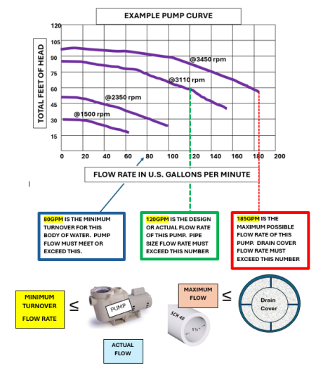
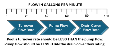
☐ The pump must be capable of meeting the minimum turnover rate.
☐ Pumps must not exceed the maximum allowable flow rates for the pipes or drain covers at the lowest Total Dynamic Head (TDH). 1
☐ Variable‑speed pumps may be programmed so they do not exceed maximum flow rates dictated by pipe size. The flow setting must be established and password‑protected to prevent tampering.
☐ New pumps shall have both a pressure gauge and a vacuum gauge installed.
Links in this section relate to Body
☐ Drain covers must be on‑site during the pre‑plaster inspection.
☐ Main drain, booster, and feature suction covers must each be capable of accommodating 100% of the pump’s flow capacity at 0 feet of head.
☐ Equalizer covers must be capable of accommodating the skimmer flow.
☐ Drain covers that are discontinued or no longer supported by their manufacturers will not be accepted.
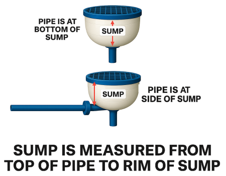
☐ Drain covers must be installed according to the manufacturer’s instructions, including requirements for sump size, pipe orientation (bottom or side connection), and flow ratings.
☐ Suction outlet sumps and piping must be free of water and debris and must be fully visible for inspection.
Note 1: Sumps are measured from the top of the pipe to the underside of the drain cover see figure below.
Note 2: Some larger suction outlet assemblies require certification by a registered design professional when a field‑built sump is used (e.g., Lawson Super Sump and Evoqua covers).
Figure 1
☐ Some channel drain covers, such as the Aquastar 32CDFL model, can no longer accommodate a single-pipe configuration according to the manufacturer. As a result, our agency will not accept certain channel drain models installed with a single pipe. Acceptance will be based on the most current manufacturer specification sheets.
☐ Existing bodies of water with single drains and SVRS devices—or split drains that cannot be verified as compliant—with planned remodeling will be required to split the drains.
☐ Some suction outlet covers may be installed less than three feet apart if they are located on different planes. Always follow the cover manufacturer’s installation instructions.
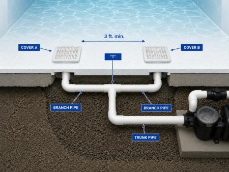
☐ When splitting drains, the covers must be installed a minimum of three feet apart, measured center‑to‑center, and connected with a “T” configuration.
- The T, or “branch” piping, must be exposed during pre-plaster inspection when splitting drains.
- The drain cover flow rating must meet or exceed the pump capacity at maximum speed (3450rpm), with the lowest resistance (0 TDH, if TDH is unknown or not verified).
- The branch piping must be of a size to ensure the proper flow rating of the drain cover (branch piping size determined by drain cover specifications).
- The trunk piping size must be able to accommodate the design flow rate or minimum turnover, whichever is higher, at 6 feet per second. The pump flow can be adjusted during operation to accommodate the pipe size if necessary.
☐ Wall‑mounted inlets must be round and smooth.
☐ Wall‑mounted inlets must not protrude more than 1.25 inches from the wall surface.
☐ Floor‑mounted inlets must be flush with the pool bottom.
Regardless of the scope of work or existing site conditions, all steps and ladder configurations must comply with current requirements. Adjustments or modifications to existing steps may be necessary to achieve compliance.
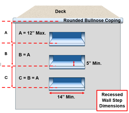
Riser measurements for wall steps and entry steps are taken from the deck, not from the top of coping or waterline.
Pools/Spas/Waders Built Before 2012:
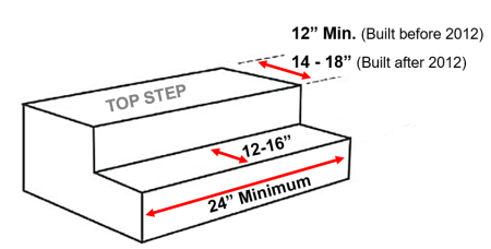
☐ Top step (straight) tread shall be a minimum of 12 inches wide (no maximum).
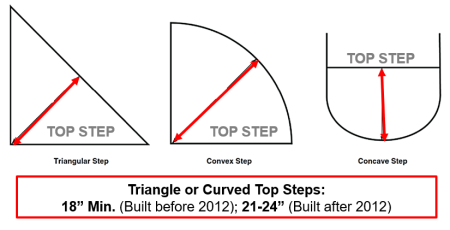
☐ Top step (rounded or triangle) tread shall be a minimum of 18 inches wide (no maximum).
Pools/Spas/Waders Built After 2012:
☐ Top step (straight) tread shall be 14–18 inches wide.
☐ Top step (rounded or triangle) tread shall be 21–24 inches wide.
All Years Built:
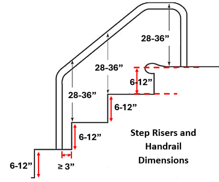
☐ Risers must be 12 inches or less, and must be uniform from shell to step, step to step, and step to deck.
☐ Treads (other than the top step) must be uniform and no greater than 12 inches wide.
☐ For waders where the distance from the deck to the shell exceeds 12 inches, a step must be installed. The step shall:
– be a minimum of 2 feet wide,
– have a 14–18 inch tread, and
– have a 12 inch or less riser, uniform from shell to step and step to deck.
☐ Construction tolerance is ± ½ inch, per code.
☐ Entry step handrails must be 28–36 inches above the step treads.
☐ Handrails and ladders must be in place and secure for the pre-plaster inspection.
☐ Entry steps must maintain a uniform shape from top to bottom.
☐ Regardless of the scope of work or existing conditions, spa remodels must include a fully functioning emergency shut‑off switch.
☐ The switch must be clearly labeled with one‑inch high lettering.
☐ The switch must deactivate all pumps connected to the spa (circulation, booster, and feature pumps, if present).
☐ The switch must be visible from the spa. For newly installed emergency shut-off switches, the switch must be installed within the pool enclosure, and within 15 feet of the spa entry steps in travel distance
If replacing depth markers, the following requirements must be met. Existing depth markers will also be evaluated for condition, legibility, and general safety during inspection.
☐ Depth markers shall have four-inch-high lettering.
☐ Abbreviations shall be “FT” and “IN”.
☐ Depth markers must be installed on the waterline and on the deck within three feet of the water’s edge.
☐ Depth markers shall be accurate within six inches, as measured at the waterline.
☐ Deck depth markers must be slip-resistant, and waterline markers must be smooth.
☐ No‑diving symbol markers installed on deck must be adjacent to all depth markers at six feet and shallower, including spas and waders.
☐ A minimum of two depth markers with no‑diving symbols is required for spas and waders.
Unless black or dark blue tiles are being installed, it is strongly recommended that a sample of waterline or trim tiles be submitted to your plan checker for evaluation prior to installation.
☐ Waterline tiles shall be contrasting in color, smooth, and cleanable.
☐ Trim tiles shall be contrasting in color and slip‑resistant on steps and benches.
☐ Depth‑marking line tiles (for pools deeper than five feet) shall be a straight line, contrasting in color, slip‑resistant, and 4–6 inches wide at the 4½‑foot depth.
☐ Lane‑marking tiles shall be slip‑resistant and shall not exceed 12 inches in width.
☐ Regardless of the scope of work, the recirculation system must have a flow meter installed on the return line.
☐ The flow meter must be legible.
☐ The flow meter must provide readings within the pool’s required turnover rates.
New and existing coping must comply with the following requirements:
☐ Overhang shall be 1–2 inches.
☐ Edges shall be rounded and slip‑resistant.
☐ Coping must slope away from the pool.
☐ Maximum thickness at the handhold shall be 2.5 inches.
☐ Coping must be flush with the waterline/shell.
An approved list of coping can be found here.
Links in this section relate to BodyRegardless of the scope of work, fencing and gates must comply with the following requirements:
☐ The fence shall be a minimum of five feet high overall.
☐ The fence shall not contain gaps greater than four inches.
☐ Horizontal climbing surfaces (inside or outside the enclosure) must be at least four feet apart.
☐ No climbing footholds are permitted within a five‑foot arc measured from the top of the fence.
☐ Gates shall be self-closing and self-latching.
Learn more by visiting Pool Safety | Orange County California - Health Care Agency
Links in this section relate to Body☐Requirements below apply to new chemical feeders and controllers. Existing units will be evaluated on a case‑by‑case basis. All feeders and controllers must be NSF‑50 certified for commercial use.
☐ For an approved list of feeders, visit:
http://publichealth.lacounty.gov/eh/docs/inspection/approved-pool-equipment-list.pdf
☐ For an approved list of controllers, visit:
https://info.nsf.org/Certified/Pools
☐ Feeders must be capable of providing three pounds of chlorine per 10,000 gallons of pool water per day.
Requirements below apply only to new filters. Existing filters will be evaluated on a case‑by‑case basis.
☐ Filters must be NSF‑50 certified for commercial use.
☐ Filters must be provided with valves for backwashing.
☐ Filters must accommodate the total flow of all circulation pumps, based on the manufacturer’s stated flow rates for the selected filtration media.
☐ Filter backwash must be indirectly drained to the sewer.
☐ DE filters must backwash through a separation tank.
☐ Cartridge filters require an approved wash‑down pad with drainage to the sewer.
☐ All filters must have a pressure gauge with a clean start‑up reading noted.
Resources
| File | Size | Last Modified |
|---|---|---|
| Approved Coping.pdf | 884.97 KB | May 11, 2026 |
| Maximum GPM Capacities of Pipes.pdf | 10.53 KB | May 12, 2026 |
| CCDEH 2023 Public Swimming Pools and Spas_0.pdf | 1.68 MB | May 12, 2026 |
| Pentair Engineering Data Sheet 2025-2026.pdf | 688.49 KB | May 12, 2026 |
| Final Checklist for Aquatic Facilities 6.9.2026.pd... | 578.5 KB | June 9, 2026 |
| FINAL INSPECTION CHECKLIST FOR SPLASH PADS 5.19.20... | 121.04 KB | July 1, 2026 |